Solidworks Drawing View Perpendicular to Plane
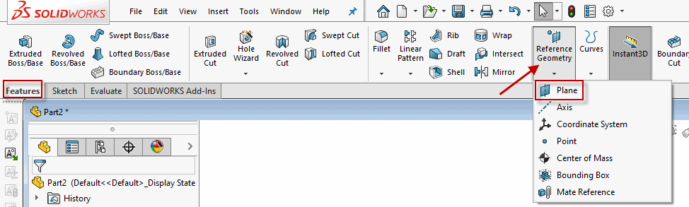
Reference Geometry includes reference planes, axes, coordinate systems, and points. In this blog, we will discuss the many ways of creating and defining Reference Planes if you lot need to utilize planes other than the default Top, Right, and Front Planes.
The Reference Geometry command lives on the Features toolbar, but you can also access it from Insert > Reference Geometry.
When the Reference Plane PropertyManager comes upward, you will notice that there is a lot of freedom for defining references and constraints and little instruction on the ways yous can create planes. The message will change from a yellow "Select references and constraints" (meaning you do non accept enough references even so) to a greenish "Fully Defined" (when you lot are able to create a airplane). The bulletin can likewise turn red if "Current combination of references and constraints are not valid".
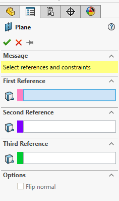
As y'all start selecting edges, faces, planes, or points every bit References, more options will announced based on your choices.
These are the various means you can define a reference airplane and we will look at an example of each one:
- Commencement Altitude
- Coincident with 3 vertices
- Ancillary with a line and a vertex
- Angle
- Parallel
- Tangent and Parallel
- Tangent and Perpendicular
- Mid Plane
- Perpendicular at a Point
- Create a plane parallel to the screen
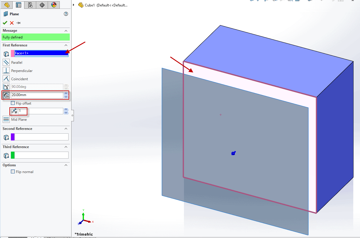
Start Distance
To create an Offset Plane, select a planar face or plane that you lot want to offset from and specify the commencement distance. Select the Flip offset push button if you need the airplane to exist created in the reverse direction. Y'all tin can also increase the number of planes to create equally spaced from the start reference to easily create multiple planes at once. In this scenario, I left the number of planes as 1. Click the green check mark to create your aeroplane.
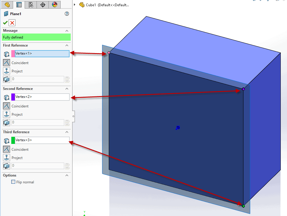
Coincident with 3 Vertices
To create a Coincident Reference Airplane, you demand to select three vertices to fully define the new plane. Once 3 vertices and the Coincident buttons are selected, the Fully Defined bulletin will appear in green and yous tin can choose the green bank check mark to create the plane coincident to all iii selected vertices.
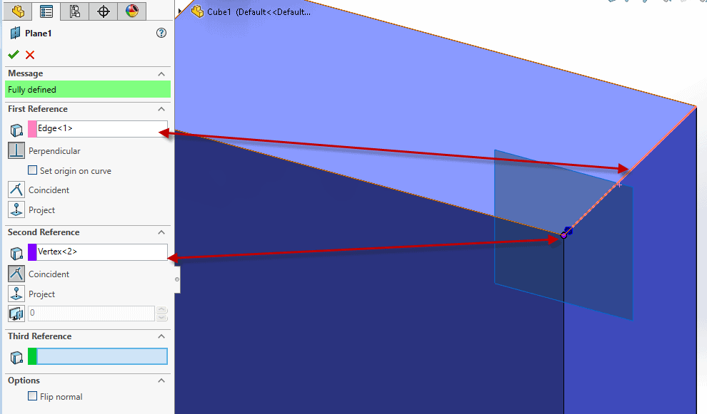
Coincident with a Line and a Vertex
Similarly, you can likewise create a Coincident Reference Aeroplane by selecting a line or edge and a vertex. In this case, the reference plane will exist created perpendicular to the pinkish edge and coincident to the purple vertex.
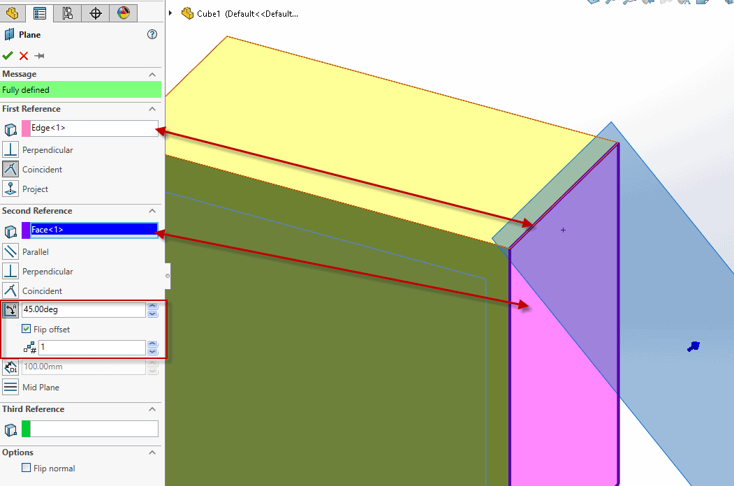
Angle
To create an Angled Aeroplane, you need to select a planar face or plane and an edge or axis to fully define the reference plane. Be certain to choose the Angle button on the planar face reference to be able to specify the degrees at which you want the plane to exist created and to have the ability to Flip offset and create multiple instances of the aeroplane.
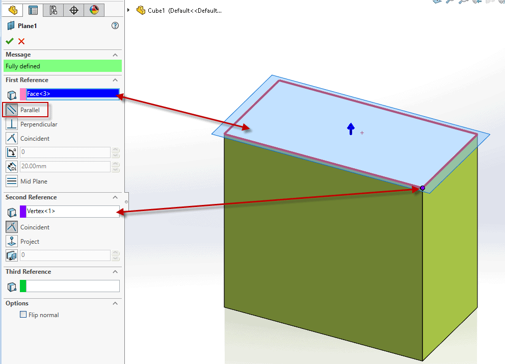
Parallel
Parallel Reference Planes tin be created when a confront and vertex are selected, and the Parallel button is chosen in the PropertyManager nether the face reference. This will create a airplane parallel to the face and coincident to the vertex.
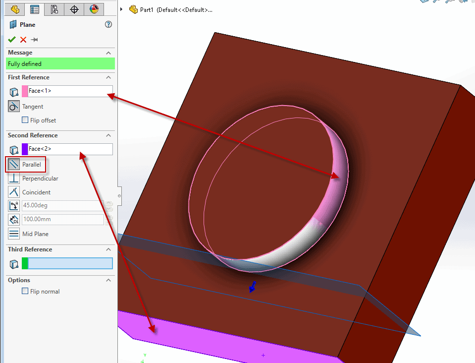
Tangent and Parallel
Tangent and Parallel Reference Planes are fully defined when a cylindrical face and a planar confront or plane are selected with the Parallel button chosen under the planar confront. This will create a plane tangent to the cylindrical face up and parallel to the planar face.
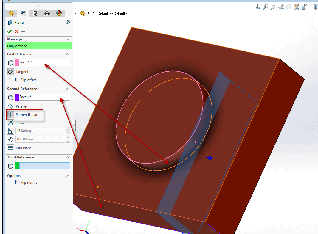
Tangent and Perpendicular
Similarly, if you choose a cylindrical face up and a planar face or plane with the Perpendicular push button chosen nether the planar confront, this will create a plane tangent to the cylindrical face and perpendicular to the planar face.
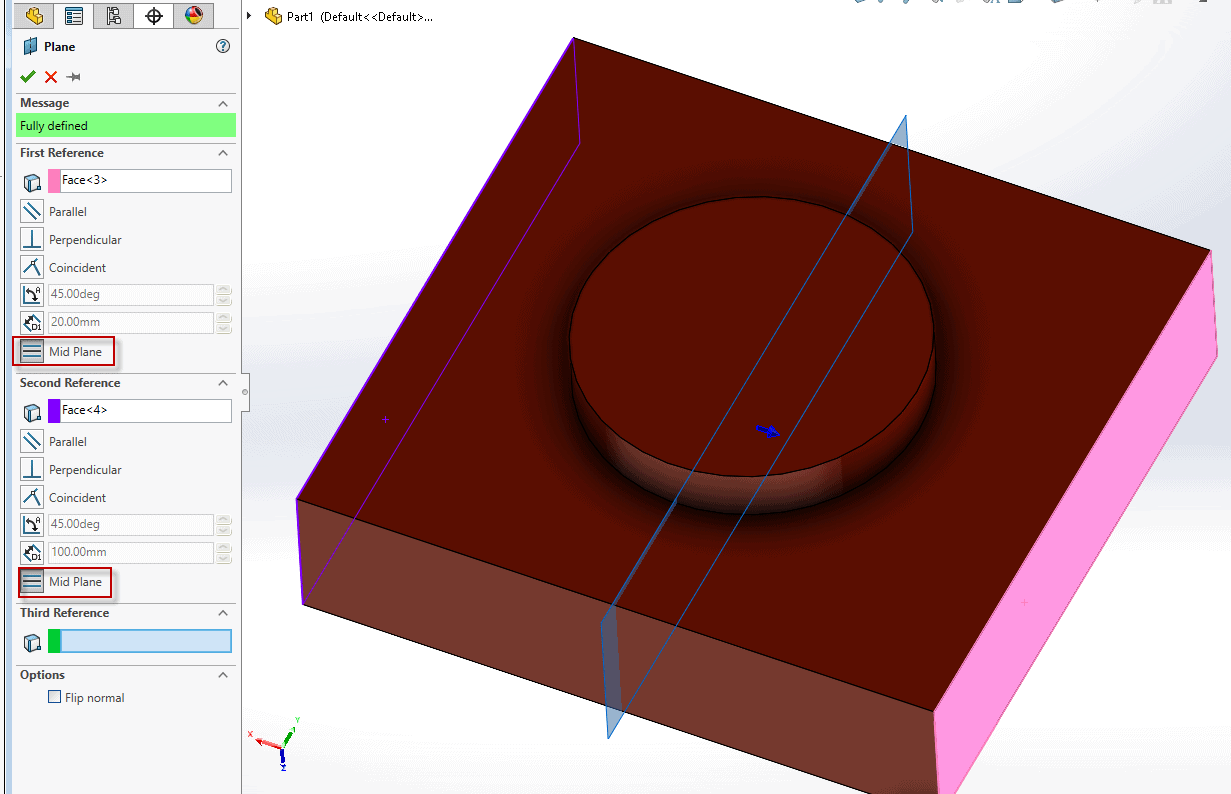
Mid Plane
Mid Plane Reference Planes are an like shooting fish in a barrel style to create a reference plane that stays centered between two faces or planes. To create this plane, simply select ii planar faces with Mid Plane selected. In this case, I chose the left and right faces to create the blue midplane in the image.
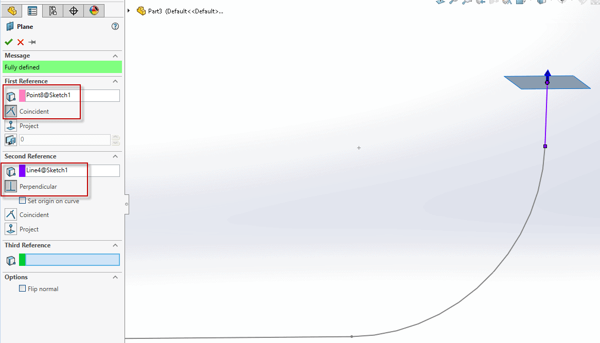
Perpendicular at a Bespeak
This example is one of the most useful reference planes especially when creating lofts or sweeps. To create a reference plane perpendicular to a indicate, create a sketch and cull a line and an endpoint in the Reference Plane Holding Managing director. From here, you have a aeroplane that can hands be used to create a profile of a sweep along your sketch.
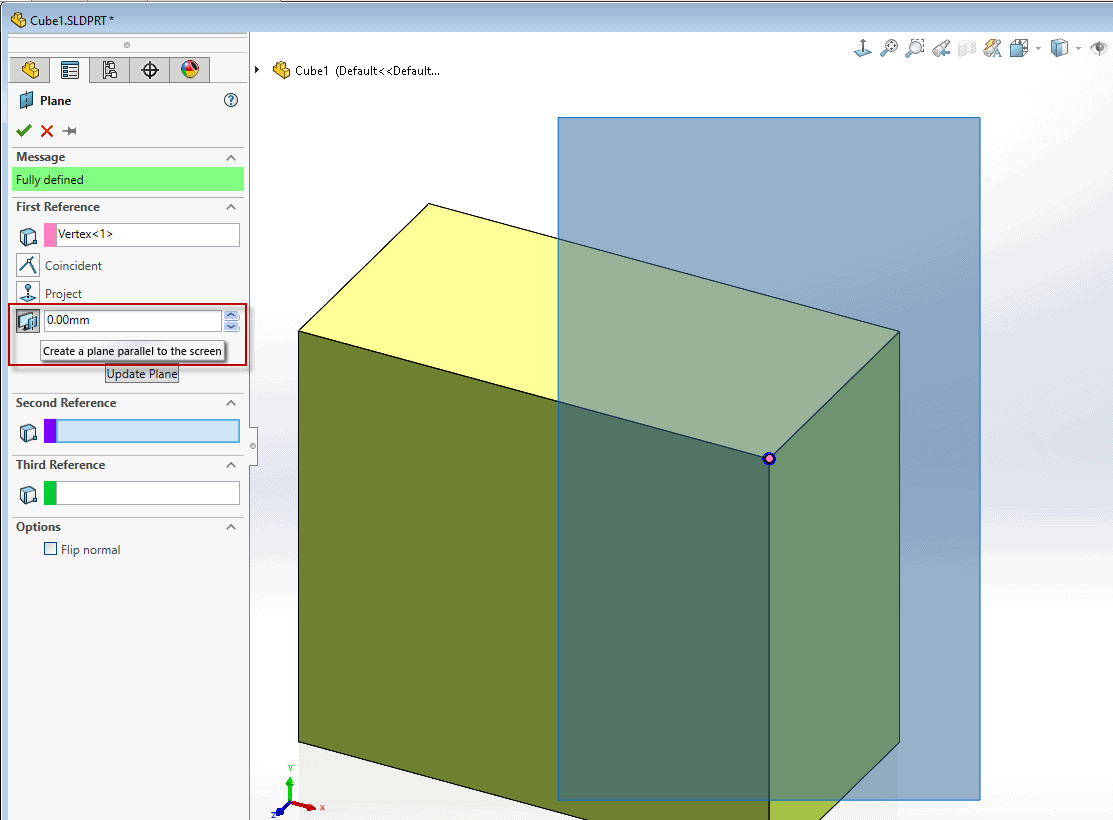
Create a plane parallel to the screen
Finally, yous tin create a aeroplane parallel to the screen by selecting a vertex and choosing "Create Plane Parallel to Screen", and optionally, an offset distance.
I hope this gives you lot a better understanding of ways to create Reference Geometry Planes to brand you more efficient in SOLIDWORKS!
Nicole Kelley
Support Engineer
Computer Aided Engineering science, LLC
revelestwomithe1956.blogspot.com
Source: https://www.cati.com/blog/basics-of-solidworks-reference-geometry-planes/
0 Response to "Solidworks Drawing View Perpendicular to Plane"
Enregistrer un commentaire